


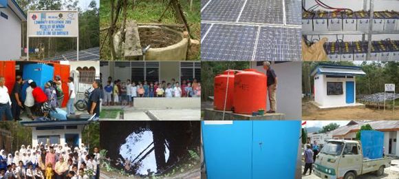







How to integrate chemical-free filtration with existing pump systems
Retrofitting a chemical-free water treatment unit into an existing pumping installation can improve water quality without replacing the entire network. The key is to treat filtration as part of the hydraulic system rather than as an isolated appliance. Flow rate, pressure, pipe diameter, control logic, backwash requirements, and water chemistry all influence the result.
Chemical-free filtration may use aeration, oxidation, catalytic media, adsorption, membrane processes, or combinations of these methods. Depending on the source water, the system can target iron, manganese, arsenic, uranium, bacteria, pesticides, turbidity, or other contaminants. The appropriate process must be selected from laboratory results and operating conditions, not from contaminant names alone.
A careful integration protects the existing pump, maintains reliable service pressure, and makes maintenance predictable. It also creates a practical path for municipalities, farms, industrial facilities, buildings, and mobile installations that need cleaner water with limited chemical handling and energy consumption.
Start with the source water and duty point
Begin by documenting the existing pump system. Record the pump model, rated flow, discharge pressure, suction conditions, operating hours, pipe sizes, elevation changes, storage tanks, pressure vessels, valves, and points of use. A pump that performs well in a simple transfer application may not provide enough pressure once a filter, control valve, aeration stage, and backwash circuit are added.
Water analysis should cover both regulated contaminants and parameters that affect filtration. Iron and manganese may appear in dissolved or particulate form, while arsenic can be associated with iron particles or remain dissolved. pH, alkalinity, hardness, temperature, turbidity, dissolved oxygen, organic matter, and bacterial activity can all change media performance.
The oxidation stage deserves particular attention when iron or manganese is present. A useful explanation of the oxidation process shows why contact time, oxygen availability, and media characteristics must be matched to the raw water. These factors determine whether contaminants are converted into particles that the filter can capture.
Match the filter to the pump curve
Every treatment component creates resistance. The filter vessel, internal distributors, media bed, control valve, fittings, and downstream pipework together produce a pressure drop that varies with flow. Compare the total dynamic head required by the treatment train with the pump curve at the intended operating point.
If the existing pump cannot overcome the added head, the system may deliver too little water, cycle excessively, or operate outside its efficient range. Increasing pump speed is not always the best answer. It can raise energy consumption, increase wear, and push the filter beyond its design flow. A larger pump may also create excessive velocity through the media, reducing contact time and causing media disturbance.
The most reliable arrangement preserves a stable design flow. A variable-frequency drive can help when demand changes substantially, while a flow-control valve can protect the filter from short periods of excessive demand. Where a booster pump is needed, position and controls should be selected so the filter receives consistent pressure without creating negative pressure at the inlet.
Build the hydraulic connection carefully
A typical retrofit includes an inlet isolation valve, pressure gauges before and after the filter, a treatment vessel, a treated-water outlet, a drain connection, and a bypass. Depending on the process, it may also need an air injector, contact tank, sediment prefilter, ultraviolet stage, storage tank, or polishing unit. Install unions or flanged connections where the equipment may need to be removed for service.
The bypass should be designed for controlled maintenance, not for routine delivery of untreated water. Clearly identify each valve and consider a lockable arrangement to prevent accidental bypass. Check valves can stop reverse flow through the media, while pressure-relief protection may be necessary if a downstream valve can isolate a pressurized vessel.
| Integration point | What to verify | Typical corrective action |
|---|---|---|
| Pump capacity | Flow and head at the treatment duty point | Adjust speed, add a booster, or select a lower-resistance process |
| Filter pressure drop | Clean and loaded-bed pressure | Increase vessel size, reduce flow, or schedule cleaning |
| Pipework | Diameter, material, and connection standards | Add reducers, flexible connectors, or compatible fittings |
| Backwash supply | Flow, pressure, drainage, and disposal capacity | Add a storage tank, larger drain, or dedicated backwash pump |
| Control system | Signals, interlocks, and restart behavior | Add a controller, pressure switch, flow meter, or alarm |
| Water quality | Raw and treated contaminant levels | Modify pretreatment, media, contact time, or polishing |
Drain capacity is frequently overlooked. Backwashing can require a short, high-flow discharge that is much greater than the normal treated-water flow. The drain must handle this volume without flooding, siphoning, or creating a cross-connection risk. Air gaps and appropriate backflow protection help keep wastewater separate from potable supplies.
Provide the right oxidation and contact conditions
Chemical-free iron and manganese removal often depends on exposing water to oxygen before it reaches the filter. This can be achieved with an air-injection device, an aeration tank, a venturi, or another oxygen-transfer arrangement. The pump system must provide enough pressure and flow for the selected method, and the contact volume must reflect the actual residence time at peak demand.
If the water contains gases, volatile compounds, or high organic loading, aeration may require ventilation or additional treatment. Air injection can also introduce bubbles that interfere with downstream measurement or cause air binding in pipework. An air-release point, suitable vessel orientation, and correctly sized contact tank can prevent unstable operation.
Pretreatment should be placed according to the contaminant profile. Coarse sediment protection may belong before the pump or immediately upstream of the treatment equipment, while fine polishing may be more effective after the main oxidation filter. A prefilter that loads quickly can starve the pump and create a false impression that the primary filter is failing.
Coordinate backwash, storage, and demand
Many media filters require periodic backwashing to remove accumulated solids and restore bed permeability. Backwash timing should be based on elapsed time, treated volume, pressure differential, or a combination of these signals. A fixed schedule can work for stable groundwater, but variable sources benefit from differential-pressure or turbidity-based control.
The existing pump may be unable to deliver the high flow needed for backwash while also supplying the facility. A clean-water storage tank can provide a reserve, allowing backwash to occur without interrupting users. In larger installations, a separate backwash pump and air-scour system may offer better control and reduce the impact on the main distribution pump.
Discharge water must be managed responsibly. Depending on local requirements and contaminant concentration, it may need controlled disposal rather than release to a surface drain or agricultural area. This is especially important when the filter concentrates arsenic, uranium, pesticides, or other substances in the backwash stream.
Connect controls, monitoring, and protection
A retrofit should have a clear sequence for startup, normal operation, backwash, alarm, and shutdown. Useful signals include inlet and outlet pressure, flow, tank level, valve position, pump status, and water-quality measurements where appropriate. Interlocks can stop the pump if a vessel is isolated, a tank is empty, or a critical pressure condition occurs.
For potable water applications, incorporate sampling points before and after treatment. Initial commissioning samples verify removal performance, while periodic testing confirms that the system remains within specification. Online turbidity, conductivity, oxidation-reduction potential, or contaminant-specific instruments may be justified for larger or higher-risk installations.
Electrical and control integration should suit the existing standard. A small building may need a straightforward pressure-controlled panel, while a municipal or industrial system may require remote monitoring and fault reporting. Low-energy equipment can help reduce operating costs; the company’s information on low-energy operation provides useful context when comparing pump duty, treatment stages, and lifecycle consumption.
Recommendations for a dependable retrofit
A practical integration process should keep the design evidence-based and serviceable. The following actions reduce commissioning problems:
- Test the raw water under representative seasonal and operating conditions.
- Plot the complete pump curve against the filter’s clean and loaded pressure drop.
- Reserve adequate flow, pressure, and drainage capacity for backwashing.
- Install gauges, sampling points, isolation valves, and a controlled bypass.
- Commission at several demand levels and document treated-water quality.
Plan for maintenance from the beginning. Define how media will be inspected, how valves will be serviced, where replacement parts will be stored, and who will respond to alarms. Operators should have a simple record of pressure readings, flow, backwash frequency, and laboratory results so gradual changes are visible before they become failures.
A phased approach can be useful when the existing installation is complex. Start with hydraulic verification and a pilot or monitored treatment stage, then add automation, storage, or polishing equipment as the operating data supports it. This avoids over-sizing while leaving room for future demand and stricter water-quality requirements.
Move forward with a measured design
Integrating chemical-free filtration with an existing pump system is a coordinated engineering task involving water chemistry, hydraulics, controls, maintenance, and safe discharge. When these elements are assessed together, the retrofit can deliver reliable contaminant removal without unnecessary chemical storage or excessive energy use.
Swiss Cleanwater Group’s water-treatment history offers further background on the development of treatment approaches and their practical applications. For a project-specific design, share the raw-water analysis, pump data, daily demand, peak flow, pressure requirements, and available installation space with a qualified treatment specialist. That information allows the filtration train, controls, and supporting equipment to be matched to the real operating conditions.
SCM 24
|
|
Cleans 24.000 liters per day
|
SCM 60
|
|
Cleans 60.000 liters per day
|
Video: How it works
The SCG Advantage
Our market-leading, water cleaning solutions have many advantages. To read more click the items below:
No Chemicals
Our machines and technology does not use any chemicals, at all.
Read more...
No Waste Water
Our machines do not waste any water. Yield = 100%.
Read more...
Low energy use
Uses 50 times less energy than a Reverse Osmosis Machine.
Read more...
Low ownership cost
Lower maintenance and operation costs due to our technology.
Read more...
Easy to install
Simple "plug and play" installation makes for easy deployment.
Read more...
Extremely compact
A compact system, contained in an easy to transport cabinet.
Read more...
Outperforms R.O.
SCG technologies outperform Reverse Osmosis systems.
Read more...
Faster ROI
Get a faster Return on Investment with our systems.
Read more...
Latest News
Latest Blog Posts
| Chemicals in water treatment? |
| Water storage - Whats best for keeping water clean and drinkable? |
| Case: Disaster Management Water Treatment |
Contact SCG
891 Showroom Place
Suite 101
Chula Vista, CA, 91914
Phone: +1 619-878-2730
Contact us by email